PAMRRC Layout Control System
The Current System
Our layout is currently controlled by a variant of the tried-and-true Cab and Block method. All Cab throttles are a derivative of Peter Thorne's SCR throttle, which we have found to be extremely reliable and easy to use. The most interesting part of the current system is that block power is routed thru electronically controlled relay boards. The relays and control boards, which have been working for 12 years, are compatible with the under-development computer-controlled system. To control a block, a Cab operator throws a small toggle switch on his private control panel. This switch sends a TTL signal to the block relay controller. The relay controllers resolve block-control-contention when more than one Cab tries to use the same block. All Cab panels have LEDs adjacent to the block toggle switches: Red indicates the block s in use, Green indicates that this Cab owns it. The system is mature and stable, requiring almost no maintenance.
Limitations of the Current System
The problem with Cab control, however, is that you're a million miles away from your train. Its 1950's technology, which was great then, but given the advancement of technology, leaves us wanting. Some clubs' Cabs, such as those of the Walnut Creek Model Railroad Society (which is a very cool, must-see layout), are so far away from the tracks that they need a massive lighted panel to know where their trains are. Kinda defeats the purpose of superdetailing, or even painting, your cars. The "modern" way to control trains is walkaround, and thanks to advances in technology, walkaround control is actually quite simple. Even MRC offers it, though they price-gouge for it because the average buyer perceives that it's a really high-tech, special feature. And walkaround control is addictive: once you've used it (as many of the PAMRRC members have while visiting other layouts), returning to the Cab system is pretty dull.
Additionally, on our layout, all turnouts are "locally" controlled by one or more control panels, which are located physically near the turnouts. Routing trains requires the Dispatcher to roam the layout, operating the various turnout controls manually (well, the controls are electronic, so he only has to push a button).
Finally, we have not yet created any trackside signaling. We want it, but independent signal controls (such as Circuitron's) are hardware-based: You have to buy all these different modules and wire them all together. A logistical headache, a wiring mess, and damn expensive.
What We Really Need
What we really need is computer control. A single, centralized computer running custom software could run the entire layout: walkaround throttles, power blocks, turnout controls, trackside signals, as well as really important stuff like crossing gates! And yes, I said power blocks - you may think that using the track-power block system with a computer is an odd combination: Why not command control? As a club we have decided against command control primarily because we don't believe that we can require all members to equip their already overly expensive locos with DCC receivers. It's just too expensive (particularly for Mick, who has well over 300 locomotives!). So we've decided to stay with block control, but have the computer select and power the blocks based on turnout position, block occupancy, etc. This is known as an Automatic Progressive Block system.
What We're Doing About It
We're creating the system described above. Though the complete, finished, fully operational system is not yet in place, parts of it are working. Some components are created but not fully debugged, other parts are only sketches on paper. It's a HUGE job, and has given me a great deal of respect for Bruce Chubb, who created his C/MRI using, compared to today's technology, stone knives and bearskins.
Given that I'm the person in the club who's most interested in control systems, and that I have the skill set and more importantly the motivation to actually create it, the layout control system is my project. Which is not to say that I'm the only one who's worked on it: Rich, Mick, and Stan have all pitched in. But the design is mine, and conveniently, this affords me the latitude to create anything I want without having to deal with pain-in-the-butt "committees" that most clubs are saddled with. The downside is, of course, that the project is mine, so I'm responsible for all the bugs and problems that arise. It's a worthwhile tradeoff.
Prior Art
I need to acknowledge the ideas and influence of Greg Austin, the PAMRRC's founder. In the late '70s, way before Chubb's system arrived, Greg was talking about controlling the layout with a computer. He designed a system that used a central 4-bit (Octal!) microprocessor that drove custom EPROMs to control remote items. To this day, our layout's block-numbering system is octal, with no 8's or 9's to be found anywhere! Greg never built his system, and is, unfortunately, no longer active in the club since moving too far away from Palo Alto to attend regularly.
The current version project was sparked years ago by Bruce Chubb's C/MRI (Computer/Model Railroad Interface) series in Model Railroader magazine. I myself being a Windows programmer by trade, and an electronics hobbyist, could see that Chubb had some really neat ideas. However, I felt that in trying to make his system work with all of the personal computers available in 1984, he had made the system too generic, and his hardware-centric design (he's an Electrical Engineer) was too complex. I also felt that the use of the BASIC programming language was a bit archaic and limiting, even back then. He's produced follow-on editions of his C/MRI book (now called the Universal Computer Interface), but it's still based on 1985 technology.
Note: Even if you choose not to use the C/MRI, if you're serious about using a computer to control a model RR, Chubb's book is required reading.
I created some C/MRI-like circuits, a C/MRI-compatible (but custom in that I used I/O ports instead of memory-mapping) IBM-PC interface card, I/O motherboards, and input and output daughterboards. I installed it all, wrote some (C-based) software, and tested the system. It all worked as advertised, but I found it to have one unexpected and unpleasant drawback: ZILLIONS of wires running from a centralized location to all over the layout. The underside of the layout became a wiring nightmare. Yes, the C/MRI has a serial option, but you're STILL stuck with lots of TTL-level wires. I also found that connecting all these wires to the C/MRI I/O boards was problematic: Either you solder them (a mess when you need to replace something) or you use Molex-type connectors, which gets very expensive very quickly. Finally, we also created and installed a number of Chubb's Optimized Detectors (current-sensing track presence detectors) and had generally good results with them. But again, they require MANY noise-susceptible TTL-level wires running to the centralized motherboard location(s).
My System: Distributed Layout Control
So for a long while I knew that the C/MRI wasn't what we wanted, and I kept tinkering. Then about a year ago a friend at work introduced me to the PIC microcontroller (PIC being an acronym for Peripheral Interface Controller, a chip designed specifically to do I/O work), made by Microchip. They make an extensive line of simple to use, simple to program, dirt cheap, all-in-one microcontrollers. The development S/W is free, as is technical support. I specifically gravitated to the PIC12C508, an 8 pin (yes, 8 pins!), 4MHz (1MIPS) chip that can hold programs as large as 512 instructions. Now, 512 instructions may not sound large, but my largest program to-date (which is pretty damn complex) uses less than half that.
I could clearly see that a software-emphasized system was the way to go. Fortunately, in the nearly 15 years since Chubb's system was invented, software has really evolved, and the hardware world has become more software-controlled. There's a growing number of chips available that do I/O specific tasks and can be controlled via a 2 or 3 wire serial interface, my favorite of which is the Inter-IC-Communication standard, commonly known as I2C.
I decided that the system absolutely MUST address three huge issues:
So I set out to create a software-based system that employs distributed intelligence interconnected by a cheap, easy to create, readily available wiring system. Here's what I came up with:
OK, I can hear some of you trashing the PC/Windows element, but PCs running Windows are the standard these days. Get over it.
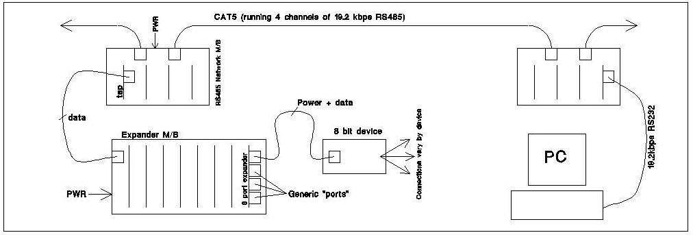
The system's core concept is to provide generic telephone-jack "ports" that any byte-device can hot-plug in to, mimicking the successful practice used in the computer networking industry, and in fact using some of it's technology. All ports and devices adhere to the same electrical and data-protocol standards, so it's a simple-to-construct "plug and play" system. Power supplies are connected only to motherboards, and all byte-devices get their power from their port connection, so power wiring is simplified and foolproof. Everything runs off of +12v DC; any special voltages (eg: +5v) are regulated locally.
The backbone of DLC is the bus, a single CAT5 cable running 4 full-duplex channels of RS485 data at 19.2kbps per channel. I chose RS485 for its noise immunity and multi-drop design. The CAT5 daisy chains between any number of strategically located "network motherboards" (NMBs), which provide a simple, expandable, plug-in interface for additional devices. The CAT5 connects to the M/Bs via RJ45 jacks and plugs. Though a bus configuration is less fault-tolerant than a star configuration, it's the standard for RS485, and the backbone is so seldom touched that I don't consider this a problem.
RS485 Network "taps" plug into any of 4 slots on the NMB. These taps can access any of the 4 channels (but are dedicated to just one), have a software-configured 8 bit address, and do the dirty work of moving packets on and off the bus. The tap passes on data packets that contain its address, and ignores all other packets. I've reserved address 0x00 for the PC-connection tap, and 0xFF for broadcasts, so there can be up to 254 taps on each channel.
The tap has an RJ8 (4-wire telephone handset) jack for connecting it to an "expander motherboard" (EMB). The EMB has 8 slots for "Port Expander Daughterboards" (PEDs). Each packet addresses a specific slot/port, and the EMB and PEDs provide the routing of the data to the correct port. The port is the generic interface that can connect to any byte-oriented-device. The byte-device is where the customization lies, and each type of byte-device performs a specific function, while interfacing to the system in precisely the same way as all other byte-devices
Here's a rough block-diagram of the DLC system (click for larger image):
In practice, the PC "talks" to the bus via a RS232 serial port, and the taps manage the addressing and traffic. The bus, having 4 separate 19.2kbps channels, has a total available bandwidth 76.8 kbps. The protocol is a simple "call and respond" transaction: The PC sends a packet out to a specific address, the addressed byte-device receives the packet, does it's specific task, and responds to the PC. All packets have the same 3-byte format: [tap] [slot/port] [data]. So the maximum capacity of the system is (4 channels) x (256 taps) x (8 expander slots) x (8 ports/slot) which is 16,000 ports, each of which handles 8 bits. Those who are familiar with the C/MRI will see the hardware has many similarities, but the big difference is in simplicity: Each hardware component performs a smaller, simpler function (although the software in each module is very complex, but you neither see nor care about that). And perhaps more importantly, the device-control circuitry is moved out to being immediately adjacent to the device being controlled. Simpler wiring, simpler diagnostics.
Here's a data-flow diagram of the PC-to-device half of a transaction (click for larger image):

Each successive block validates its portion of the address, and if correct, passes on the remaining byte(s). In the example above, the PC wants to send the value 0xFF to a device that's connected to tap 0x3F, EMB slot 2, PED port 5. All taps see the data stream, but only tap 0x3F passes on the bytes 25 FF. All other taps (eg: tap 0x25) "eat" the byte stream. The EMB passes x5 FF to the PED in slot 2 (actually 05 FF, but the PED doesn't look at the upper nibble of 05), then the PED passes FF on to port 5. Once the byte-device at port 5 has processed the data, it sends back a byte (whose value is device-specific), and the PED, EMB, and tap prepend their specific data and a 3-byte packet is sent out on the network. The PC receives it, and processes the response accordingly.
System Components
Because all of the specialization is in the byte-devices, the rest of the system is very simple. As detailed in the diagrams above, these are the components that allow the PC to talk to the byte-devices:
|
Component |
Function |
|
RS232 to RS485 Tap |
Interface PC's serial port to network bus |
|
RS485 Network Tap |
Interface EMBs to n/w bus, perform 1-of-256 Tap addressing |
|
Network Motherboard (NMB) |
Provide power and channel-data access to Taps |
|
Expander Motherboard (EMB) |
Interface Taps to PEDs, perform 1-of-8 slot addressing |
|
Port Expander Daughterboard (PED) |
Provide generic Port interface, perform 1-of-8 port addressing |
|
Perform 8 context-specific bits of I/O |
All byte devices do the following: Receive a byte, do some processing, return a byte. Some devices consider the received byte as junk, only using it as a trigger for processing. Some devices have nothing to return, but do so anyhow in order to honor the protocol. A selected list of devices I've created so far, and how they handle data:
|
Device |
Received Byte |
Returned Byte |
|
Signal Driver |
Lamp aspects |
Junk (returns rx'ed byte for simplicity) |
|
8-Block Occupancy Detector |
Junk (triggers processing) |
Bitmask of block states |
|
8-bit Generic TTL Input |
Junk (triggers processing) |
Bitmask of 8 input states |
|
8-bit Generic TTL Output |
Bitmask of 8 output states |
Junk (returns rx'ed byte for simplicity) |
|
8-bit Generic TTL I/O |
Bitmask of 8 output states |
PBitmask of 8 input states |
|
8 Turnout Controller |
Position settings for turnouts |
Positions of turnouts |
|
Digital Power Throttle |
Speed setting & Direction |
Power consumption (Digital ammeter) |
|
Digital Walkaround Throttle |
Junk (triggers processing) |
Speed setting & Direction |
One additional, very important feature of these devices is that, on power cycling, they remember their last setting and initialize themselves to it. This means that the layout will "boot up" in the precise state that it had upon power-off.
I'll create more devices as I think of them and/or need them. If you have any ideas, let me know!
PC Software
As mentioned above, the central controller of the system is a PC running a function-specific MS Windows program ("control app"). Separate PCs could each control each of the 4 bus channels, or a single PC, with 4 COM ports, could control all 4 channels simultaneously. The most basic function of the control app is to constantly monitor all its input devices, crunch the data to determine the layout's state, then drive all the output devices. I also intend the layout's dispatcher to control the layout via a Windows app, so the dispatcher app works in concert with the various control apps to configure the layout. Throwing turnouts is as easy as clicking the mouse.
The control and Dispatcher apps are the least-compete parts of the system. I've written proof-of concept apps, but I've done nothing beyond that. There's a LOT of work to be done in this area, but fortunately it's the easiest to create, so I'm not concerned.
|
Manufacturer |
Part |
Description |
|
8-pin, 8-bit CMOS microcontroller |
||
|
Remote 8-bit I/O expander for the I2C bus |
||
|
Low-Power, Multi-Channel, serial 8-bit ADC |
||
|
Low-Power, RS-485 Transceiver |
Notes:
Maxim has the best technical website EVER! Easy searches, and FREE samples!
Philips has a terrible website, and whoever created it should be shot.
Suppliers:
|
Good prices, smaller selection |
|
|
Somewhat higher prices, HUGE selection |
Useful Books:
All books listed can be found at Amazon.com
|
Title |
Author |
ISBN |
|
0079126391 |
||
|
Model Railroad Electronics: Basic Concepts to Advanced Projects |
0890241465 |